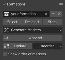
Formations panel
With the Formations panel of the Formations tab you can import, generate, create, update or remove formations, select, deselect and sort drones in formations, and you can also add formations to your storyboard.
Create Takeoff Grid
The Create Takeoff Grid button helps you set up your first and last formations, the takeoff and landing grid. The takeoff and the landing grid is assumed to be the same by default, but you can change them later on if needed.
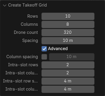
For a regular takeoff grid you can define the number of rows and columns, the exact number of drones and the spacing between them. Once you press OK, a rectangular grid is created with the specified parameters.
For advanced settings enable the Advanced checkbox.
If you wish to have a separate column and row spacing for your basic takeoff grid, enable the Use separate column spacing checkbox and setup a separate column spacing.
If you wish to takeoff (and land) in layers, you can also define a more complex takeoff grid with slots, where each slot contains more than one drone with typically, but not necessarily smaller spacing (see the Intra-slot parameters). With such a takeoff grid it will be guaranteed that only one drone will takeoff from (and land to) every slot at a time, using layered takeoff and land operations automatically.
The Create takeoff grid operator also creates all Skybrush-specific collections (Drones, Formations, Templates) that you will need for your drone show, it adds the first "Takeoff grid" entry to the storyboard and also initializes your drones in the 3D Viewport editor.
| Once the takeoff grid is created, you are free to modify the created "Takeoff grid" formation to re-arrange the placement of the drones using standard Blender operations, thus you can easily adapt the grid to the requirements of your specific takeoff area. For instance, if there are lampposts, stairs, power lines or any other obstacles in the area, you can move the affected drones to other positions by simply changing the takeoff positions in the "Takeoff grid" formation. |
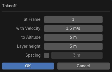
Takeoff
The Takeoff button adds a takeoff maneuver to a specified altitude and with a specified average vertical velocity from your initial takeoff grid. The start frame of the maneuver can be customized, although it is usually the same as the first frame of the scene.
If the minimum distance between drones in the takeoff grid is smaller than the given spacing parameter, the takeoff is automatically performed in layers with no drones closer to each other than the spacing.
In such cases (i.e., when you set a small spacing parameter or the takeoff grid was created with more than one drones per slot), use the layer height parameter to setup the altitude difference between additional target layers above the default layer during the layered takeoff operation.
This button should ideally be pressed right after the takeoff grid is created, but before any other formations are added. It is also possible to use the operator later after having defined the first few formations, but you must ensure that there is enough time before the first formation to perform the takeoff and get to the first formation in time.
| Skybrush requires you to specify the average vertical velocity of the drones during takeoff. This lets you gauge easily how much time the takeoff will need (e.g., taking off to 6 meters with an average velocity of 1.5 m/s takes 4 seconds), but since the drones need time to accelerate and decelerate, their maximum vertical velocity will be higher than the average velocity to compensate for the time lost during acceleration and deceleration. Make sure to take this into account in order not to overshoot the vertical velocity limits of the drones. |
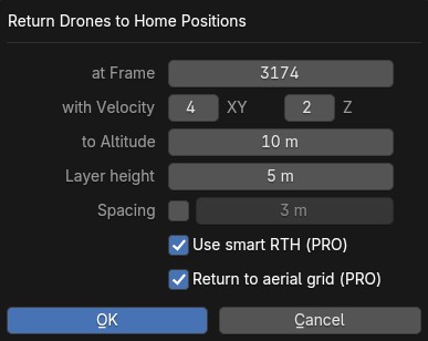
Return to home (RTH)
The RTH button performs a return-to-home maneuver with a specified average velocity from your last formation of the show. This procedure brings the drones straight above the positions where they are supposed to land to an altitude that can be specified in the operator.
If the minimum distance between drones in the takeoff grid is smaller than the given spacing parameter, the return to home operation is automatically performed in layers with no drones closer to each other than the spacing.
In such cases (i.e., when you set a small spacing parameter or the takeoff grid was created with more than one drones per slot), use the layer height parameter to setup the altitude difference between additional target layers above the default layer during the layered RTH operation.
Note that the maneuver is not performed at the specified altitude — it is initiated from the positions at the end of the last formation. However, all drones arrive to the given altitude (or layered altitude) value, above the takeoff grid.
This button should be pressed after all formations of the show are inserted to the storyboard, but before the landing entry is given.
| It is not guaranteed that each drone will land at the same position where it took off from. In the vast majority of cases, they will land at a different position in the grid. This is intentional; safe collision-free trajectories are easier and faster to design when the software is free to choose which drone should occupy which landing position. |
Smart return to home
If you intend to land each drone to its original home position, use the Use smart RTH checkbox. This feature attempts to create a special trajectory for each drone from its latest location to its original home position, without collisions, using the given spacing as minimum distance in its planner.
| This feature is not supported by our community server. To enable it, please purchase a proper license from Skybrush Shop. |
If you use the smart RTH option, you do not need to land your drones afterwards, as the landing process is an integrated part of the smart RTH maneuver. For the same reason, the layer height parameter is also neglected in this case. The altitude parameter is used to specify an altitude threshold below which the drones are guaranteed not to move horizontally.
| it is not ensured that there is a smart RTH solution for each situation. If the planner fails to perform the operation, try reducing spacing parameter or change the RTH altitude setting. |
Return to aerial grid
Use this option to return to a — possibly layered, 3D — aerial grid above home positions without landing drones afterwards.
This option is mostly useful when you design into external show formats that do not contain show from ground to ground but only from and to this floating grid. However, this option works both when you start your show from the ground or when you delete the takeoff and start your show already from such a floating aerial grid.
The algorithm behind returning to a 3D floating grid is slightly different from the standard smartRTH algorithm: it first brings the drones down to an enlarged grid (this is the only way minimum distance requirements can be ensured while drones sink through layers of other drones) and then shrinks this enlarged grid to its final form. So if you use this algorithm, make sure you have enough aerial space above your takeoff area at the given height for the enlarged grid.
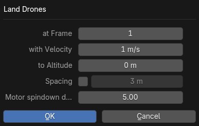
Land
The Land button lands the drones, starting from a given frame such that they move downwards in a straight line from their current position until they reach the given target altitude (ground is assumed to be at Z = 0). As usual, the average velocity of the descent can be adjusted.
If the minimum distance between drones in the takeoff grid is smaller than the given spacing parameter, the land operation is automatically performed in layers with no drones closer to each other than the spacing.
In such cases (i.e., when you set a small spacing parameter or the takeoff grid was created with more than one drones per slot), use the Motor spindown delay parameter to setup the time difference between landing layers. This ensures that drones will land close to the others within the same slot only when the motors of the neighboring drones are already stopped.
This button should be pressed after the return to home entry is inserted to the storyboard.
Selecting the active formation
Click on the Formation button to select the formation to be edited in the Formations panel.
Creating a new formation
The + button creates a new formation. Remember that formations are essentially sub-collections in your Formations collection, consisting of (stationary or animated) markers that define the desired positions of the drones in a particular scene of your drone show.
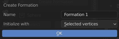
You can define a name for your new formation and choose how it should be initialized:
- Empty
-
Creates an empty formation (useful as a placeholder into which markers are generated later on)
- Current positions of drones
-
Creates a formation that contains one empty mesh for each drone, placed exactly at the current position of the drone. You can use this option to create a "snapshot" of the drone swarm at a given frame and use it again as a formation later on in the show.
- Selected objects
-
(Only in Object mode) Creates a formation that contains the currently selected objects. If the locations of the objects were animated, the formation will be animated as well. Removing any of these objects from the scene will also remove them from the formation.
- Current positions of selected objects
-
(Only in Object mode) Creates a formation that contains one empty mesh for the position of each selected object. The empties are added to the formation, but the objects themselves are not — therefore, even if the objects were animated, the formation will only take a snapshot of the objects at the current frame. You are then free to remove the objects from the scene without affecting the formation.
- Current positions of selected vertices
-
(Only in Edit mode) Creates a formation that contains one empty mesh for the position of each selected vertex of the currently edited object.
When the number of markers in the created formation is different from the number of drones in the show, a warning message will appear to indicate the formation size mismatch.
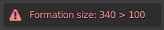
If you see such a message, try to harmonize the number of markers in the formation with the number of drones in the show, otherwise automatic transitions won’t work.
Removing a formation
Press the ✕ button to remove the selected formation from the Formations list and the Formations collection entirely. Meshes that were part of the formation but that were not referenced from anywhere else in the Blender scene will also be removed from the scene. If you want to keep them, put them in another collection first or by assigning them to a fake user in Blender.
Selecting and deselecting a formation
The Select button on the Formations panel adds the selected formation to the current selection in Blender. Similarly, the Deselect button removes the markers of the selected formation from the current selection.
Since formations may contain meshes as well as vertices of meshes as markers, you may not necessarily see the result of the selection immediately. If you are in Edit mode and you attempt to select a formation that contains meshes, you need to switch back to Object mode. Similarly, if you are in Object mode and you attempt to select a formation that contains vertices a markers, you need to switch to Edit mode to be able to interact with the selected vertices.
| If you are in Object mode and the formation being selected contains vertices only (i.e. no meshes or empties), Skybrush Studio will automatically switch to Edit mode. |
Generating markers for a formation
Once a formation is created (and preferably appended to the storybard), use the Generate Markers button to generate extra static or dynamic markers into that formation from different sources:
- From static CSV file
-
Use this option to import a previously created static formation from an external .csv file, in which each line contains the following values in order (colors are optional and assumed to have linear color space):
Name,x_m,y_m,z_m,Red,Green,Blue - From zipped CSV files
-
Use this option to import previously created animated formations or entire shows modularly from an external .zip source that contains multiple .csv files (one per drone), each containing baked trajectory and light animation in the following line format (colors are optional and assumed to have linear color space):
Time_msec,x_m,y_m,z_m,Red,Green,Blue - From zipped PATH/PATH3 files (PRO)
-
Use this option to import previously created animated formations or entire shows modularly from an external .zip source that contains multiple DSS .path or .path3 files (one per drone), each containing baked trajectory and light animation (in linear color space).
| This feature is not supported by our community server. To enable it, please purchase a proper license from Skybrush Shop. |
- From SVG file (PRO)
-
Use this option to import an SVG file to sample it with the given number of drones. Note that only simple, flat SVG files can be imported correctly, and only vector graphic shapes are supported from the SVG file, text, images and other complex formats are not supported (we support what is supported by the external
svgpathtoolsPython library). The importer tries to optimize the given number of drones to the imported shapes, which might result in ugly results if there are not enough or too many drones or if the curves are too complex. Try to simplify the SVG before importing as much as possible and experiment iteratively to find the proper number of drones for your SVG drawing! Colors of the curves are also imported.
| This feature is not supported by our community server. To enable it, please purchase a proper license from Skybrush Shop. |
- From QR code
-
Use this option to generate a static QR code as part of the show.
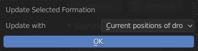
Updating a formation
Press the Update button to update the selected formation from the current selection or from the current positions of the drones. This operation is essentially equivalent to removing all markers from the formation first, followed by the addition of the selection as if you were creating a formation from scratch.
You can also update formations simply by moving the markers in 3D space using the standard tools that Blender offers. New markers can be added simply by creating empty or non-empty meshes and adding them to the appropriate sub-collection of the Formations collection, or by extending the Drones vertex group in vertex-based meshes. Unneeded markers can simply be removed from the formations the same way you would remove any Blender object from its corresponding collection.
Reordering a formation
Points in every formation have a specific order. This gets useful when staggered transitions are created between two formations and thus drones do not depart from or arrive to a given formation at the same time, but in a delayed manner, one after another, in the order they are represented in the formations.
Reordering a formation can be issued any time with opening the Reorder drop down list and selecting the preferred reordering operator. Note that reordering is instantaneous; using multiple reorder operators is possible, each one will take the current order and apply its own modifications to create the new order. The following reorder operators are implemented:
- Sort by name
-
sort by the name of items in the formation (default sorting)
- Shuffle
-
shuffle the items in the formation to a completely random order
- Reverse
-
reverse the current order
- Sort by X/Y/Z coordinate
-
sort the current order according to the X/Y/Z coordinate value of each point in the formation
- Every 2nd/3rd/4th
-
pick every 2nd/3rd/4th item and repeat until all items are assigned to the new ordering
- Ensure safety distance
-
pick the first item, then iteratively pick the next item that is far enough from all previous items picked (based on the distance limit set in the safety settings). When the list is exhausted, start from the beginning with the remaining items, ignoring the items picked in the previous round(s) in distance calculations. Repeat the process until every item is processed. The result is an ordering where consecutive items strive to respect the distance limit.
| to visualize the current order of a formation, enable the Show order of formations checkbox, which will connect all points in the formation with linear line segments between each consecutive point in the current order colored from green to red. |
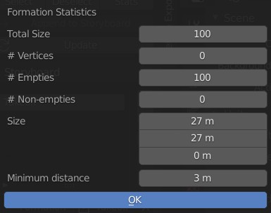
Formation statistics
Press the Stats button to show various useful statistics about the selected formation, such as the number of markers (empties, meshes or vertices), the size of the axis-aligned bounding box of the formation, or minimum distance between its markers on the current frame.
Appending a formation to the storyboard
Press the Append to Storyboard button to append the selected formation to the end of the storyboard. Skybrush Studio will calculate the time needed to move from the end of the last formation to the newly added formation, according to the current acceleration and velocity limits, and set up the start time of the new formation accordingly.