Fit the show to your venue
Setup show origin and show orientation
Show trajectories are always expressed in relative coordinates. To position your show in the real world, you need to define a geodetic origin and an orientation for your show (we are talking about outdoor shows here - for indoor shows the origin and the fixed orientation is usually fixed by the used positioning system).
The proposed show origin and orientation might be included in your .skyc show file, but it can be modified in Skybrush Live as well in several convenient ways:
-
Right click somewhere on the map and use the context menu to place your show origin to the given point.
-
Select the convex hull of the trajectories in the Map panel and i) move it around by holding the left-mouse button down while navigating; ii) rotate it by pressing Alt while navigating with left-mouse button down.
-
Click on the Setup environment checklist entry for a detailed and precise setup.
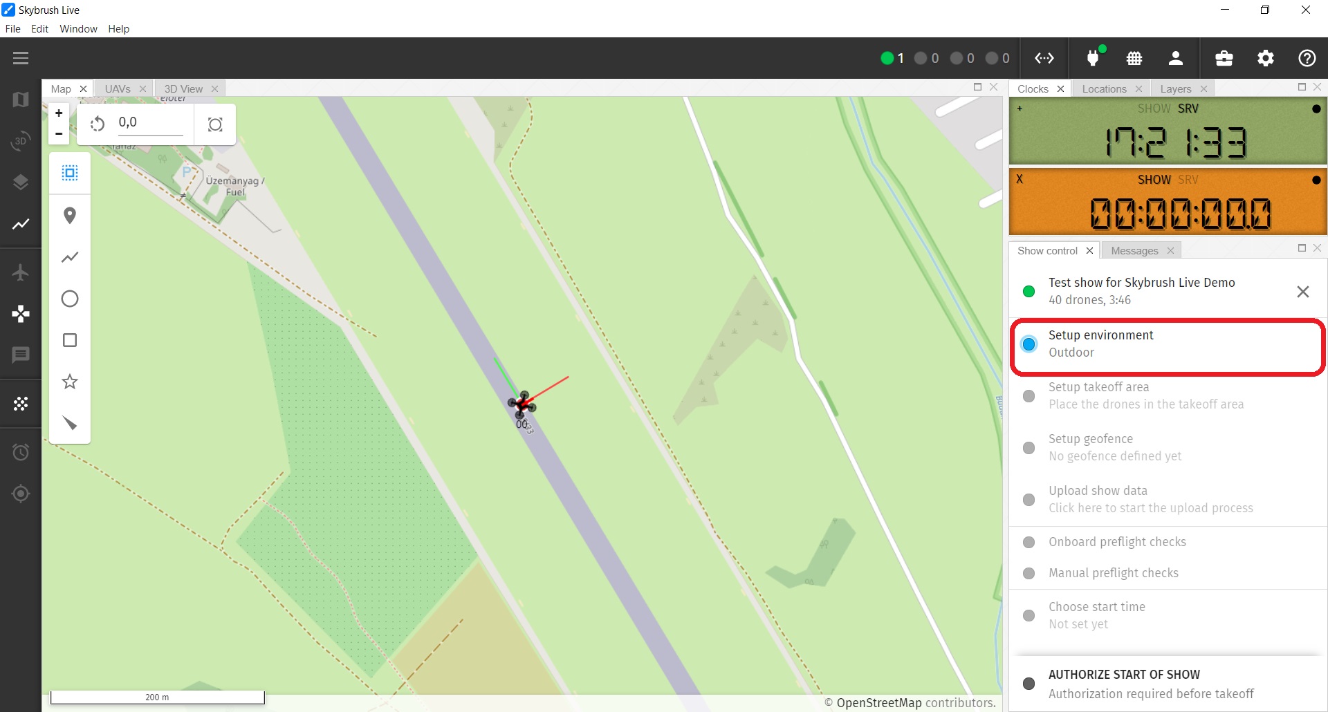
On the appearing Environment settings popup window you can enter explicite values for show orientation, origin and AMSL reference manually.
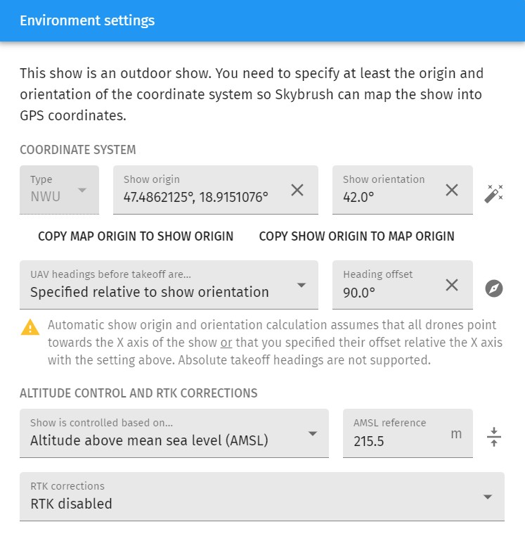
| Try the magic wand button on the right side next to show origin and orientation property to auto-fit the show origin and orientation to the actual positions of your active drones seen by Skybrush Live. Note that the auto fit algorithm will assume that your drones are aligned with the show orientation according to the drone heading settings detailed below. |
Setup desired drone headings on the ground
Besides the show origin and orientation you can also define the front direction of your drones (i.e. their heading on the ground) relative to global coordinates or relative to the show orientation.
| Use the magic compass button on the right side next to the heading settings to calculate the common heading value from the average headings of the drones currently out on the field. |
Setting up the desired heading of the drones is useful for safety validation purposes. Skybrush Live detects misaligned drones with bad orientation compared to the given settings with yellow warning or red error color in the heading column of the UAVs list and in the Setup takeoff area popup. Drone misalignment is typically caused by compass errors or drones placed on metals, wires or magnetized subsurface objects that might affect the estimation of drone orientation and thus flight stability.
Setup altitude reference
On the Environment settings popup window you can also choose between AHL- or AMSL- based altitude reference during the show.
If you use an RTK base station and you have high quality correction signals, we recommend to use absolute altitude in your flight (AMSL-based). In this case you need to setup the absolute altitude of the home/ground reference level manually.
| Press the button on the right side of the AMSL reference text box to set the AMSL reference to the average absolute altitude of your active drones. |
If you do not use an RTK system, relative (AHL-based) altitudes are preferred, as without RTK the AMSL values are poorly estimated and this can affect the takeoff and landing quality of your drones badly.
If you use an ArduCopter-based autopilot with EKF2, check the EK2_ALT_SOURCE parameter to setup your altitude calculation properly. With RTK, GPS altitude source is preferred, while without RTK barometer altitude source is preferred. If you use EKF3, set EK3_SRC1_POSZ instead. If you use more EKF3 lanes, also set the remaining EK3_SRCx_POSZ parameters as needed.
|
Enable RTK corrections
Finally, the Environment settings popup window can also be used to select your RTK correction data source to allow centimeter level positioning of your drones, but you can also set that up any time later on in the RTK Status toolbox item.
Check your setup on the map
If you succeed with all environmental settings, yellow triangles should appear on the map, showing the newly defined home positions of the show and a yellow polygon around the home positions indicating the convex hull of all trajectories.
| If you cannot see these yellow mission items, enable them from the Mission info layer in the Layers panel and/or press the Zoom to Fit button. |